Aviation Engines
0) : ?>Piston Engines
From the 1903 flight of the Wright Brothers to the mid-1940’s, the piston engine was the only power plant used for aircraft. Originally aircraft engines were built around the same design of car engines. Specifically in the design of cooling systems. Car engines are water or liquid-cooled. They rely on radiators (Heat Exchangers) in order to take air from the outside and cool the warm water coming from the engine (Figure 1).
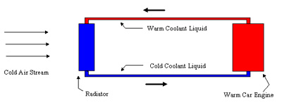
Figure 1. Schematic of a car engine cooling system.
The problem involving water cooled engines is the excess drag and weight that would be added to the plane thereby having a significant influence in aircraft performance. By 1908 this degradation of aircraft performance due to liquid-cooled systems was noticed and air-cooled engines were first introduced. The savings in weight were substantial. The air-cooled engine weight (on average) was between 30% and 40% of the weight of the liquid-cooled engine.
The first generation of air-cooled engines did not perform as well as expected. In this first generation the cylinders were arranged in a circle around a crankcase. The propeller was fastened to the front of the crankcase and the entire engine rotated! This was done to increase the air velocity over the cylinders for cooling purposes. But what made this type of engine a failure was that the gyroscopic forces were large, limiting the ability of the aircraft to maneuver. This problem was later solved by designing air-cooled engines in a similar radial arrangement, but with the engine fixed and only the propeller rotating. But liquid-cooled engines were not finished just yet, because from about 1915 onward, better designs of liquid-cooled engines were able to develop more power than air-cooled engines. So for the next 25 years, one of the major aircraft design debates concerned the relative drag, weight, and maximum power capabilities of liquid-cooled versus air-cooled engines.
Many of the best fighters of World War II were powered by liquid-cooled engines and by the mid-1940s the debate was over and air-cooled engines were the victors. One major development assisting the air-cooled engines was the development of the NACA cowling. This was an enclosure for the engine that limited the flow of air over the engine cylinders to the air actually in contact with the cooling fins of the cylinders. This advanced was very important in improving the efficiency of air-cooled aircrafts (Figure 2).
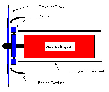
Figure 2. An improved air-cooled engine with cowling.
From the mid 1940s until today, many advancements have been made in air-cooled engines. The evolution of the propeller-based engines are called turboprops, although the only similar characteristic of today’s turboprop and the original air-cooled engines is in that both of them use a propeller in the front.
Air-Breathing Engines
Air breathing engines are also known as gas turbines and aircraft engines are referred to (wrongly) as just turbines. An aircraft gas turbine is a device in which freestream air is taken in through a designed inlet, compressed in a rotating compressor, heated in a combustion chamber, and expanded through a turbine. The gas then exits through a nozzle at a velocity greater than freestream (Figure 3). Though one can classify a piston engine as air breathing, the amount of air taken in by gas turbines is much, much greater. Therefore, we will classify gas turbine engines as air breathing engines.
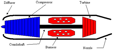
Figure 3. Schematic diagram of a turbojet engine.
Gas turbines are subdivided into four categories: turboprops, turbofans, turbojets, and prop-fans. The differences are in the speed at which they are used. In reality, the differences in these categories are due to the concepts on which these engines were created. The speed limitations are due to the limitations for the different concepts. The turboprops (Figure 4) are mainly used for cargo planes that fly at speeds typically between 300-500 mph. Its arrangement is derived from that of turbojet engine system. The only difference is that turboprops have a propeller blade and a gear box in front of the engine followed by a similar arrangement as that of a turbojet engine. The turboprop differs from the gas turbine in that the gas turbine drives a propeller. The propeller is the component which generates the thrust for propulsion – not the exhaust jet as in the turbojet case. This is the conceptual difference. The turboshaft is, by the way, in principle also a turboprop.
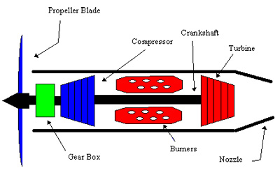
Figure 4. Schematic diagram of a turboprop engine.
The turbofan (Figure 5) is an engine system similar to the turboprop but with a smaller multiple blade fan encased in a cowling without the gear box. The turbofan is a turbojet with a fan to generate a bypass flow along the core turbojet in order to increase the mass flow. The increased mass flow enhances the efficiency of the engine. The fan is driven by the gas turbine. Note that the fan may be geared or direct driven. This engine system is used for multiple types of aircrafts such as cargo planes, passenger planes, fighter aircrafts, etc. The range of velocities for which this engine is used is typically from below Mach 1.0 (one time the speed of sound) to speeds above Mach 1.
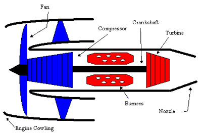
Figure 5. Schematic diagram of a turbofan engine.
The turbojet is the basic, plain, gas turbine. It is a hot gas generator with a jet nozzle to create enough kinetic energy for the propulsion. The turbojet is the most inefficient engine when compared to the turboprop and the turbofan but produces high thrusts. It consumes more fuel than its counterparts but the range of velocities at which is operated cannot be achieved by the turboprop or the turbofan. The top operational velocity is the vicinity of Mach 3.0. Among the most famous aircrafts that make use of this propulsion system are: the Anglo-French built Concorde, the Russian TU-144, and the famous American bomber B-52.
The last of the air breathing propulsion systems is the prop-fan (Figure 6). The prop-fan is a newer air breathing system. It is a combination of a turboprop and a turbofan. Its arrangement makes it the only propeller driven aircraft that is capable of pushing an aircrafts to speeds up to Mach one. Its only problem and the main reason for why it has not been incorporated into commercial aircrafts is the intensity of the noise coming from it. It has a higher efficiency than any of the air-breathing engines. It is basically a turbojet engine with a propeller in the back of the engine rather than in front like the turbojet or turbofan.
The propfan need not be a pusher – it can just as well be a tractor, just as the turboprop can be a pusher! The difference between the prop-fan and the turboprop is that in the prop-fan the exhaust jet is used for propulsion in combination with the propeller/fan. Basically, it is a turbofan engine with a higher bypass ratio (ratio of air mass going through bypass to air mass going into engine) and, possibly but not necessarily, without a fan duct. The boundary between the prop-fan and the turbofan is floating, as can be appreciated by different company’s vocabulary (e.g., unducted fan engine).
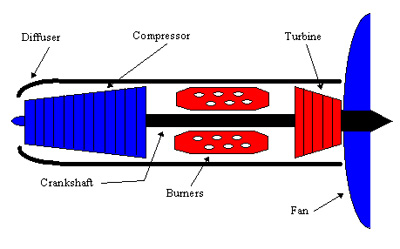
Figure 6. Schematic diagram of a prop-fan engine.
Beyond Turbojets
The turbojet is the general configuration for mostly all aircraft-related propulsion systems. But as flight speed increases beyond Mach 3.5 (3.5 times the speed of sound) the turbojet configuration becomes highly inefficient. The reason for this is that as Mach number increases and the total inlet temperature rises, so does the total inlet pressure. In the vicinity of Mach 3, the inlet pressure rise is sufficient to permit the compressor to be omitted. This would imply that there would be no need for a turbine either since the sole purpose of the turbine is to drive the compressor. The resulting engine is known as a ramjet. A ramjet is probably the simplest and yet most powerful aircraft engine. The ramjet is basically a duct with the front end shaped in the form of an inlet, the aft end designed as a nozzle, and the combustion chamber in the middle (Figure 7). While a ramjet may be operated below Mach 3, they must operate at speeds greater than Mach 3 to be competitive with turbojets.
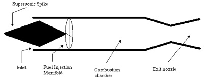
Figure 7. Schematic diagram of a ramjet.
As speeds increase beyond Mach 5, the temperature at the inlet will increase tremendously. This increase in temperature would tend to dissociate and ionize the air, a process that absorbs energy and reduces the temperature increase sought from the burning of the fuel. In order to correct this problem, a new generation of ramjets was developed known as scramjet or supersonic combustion ramjet. Very few vehicles (mostly missiles) have been fitted with this type of propulsion system.
Contact a Helicopter Lawyer
If you have been injured or a loved one has been killed in a helicopter crash, then call us 24/7 for an immediate consultation to discuss the details of the accident and learn what we can do to help protect your legal rights. Whether the accident was caused by negligence on the part of the helicopter owner, hospital or corporation, the manufacturer or due to lack of training, poor maintenance, pilot or operator error, tail rotor failure, sudden loss of power, defective electronics or engine failure or flying in bad weather conditions, we can investigate the case and provide you the answers you need. Call Toll Free 1-800-883-9858 and talk to a Board Certified Trial Lawyer with over 30 years of legal experience or fill out our online form by clicking below:
0) : ?>